Brake Chopper Circuit Diagram
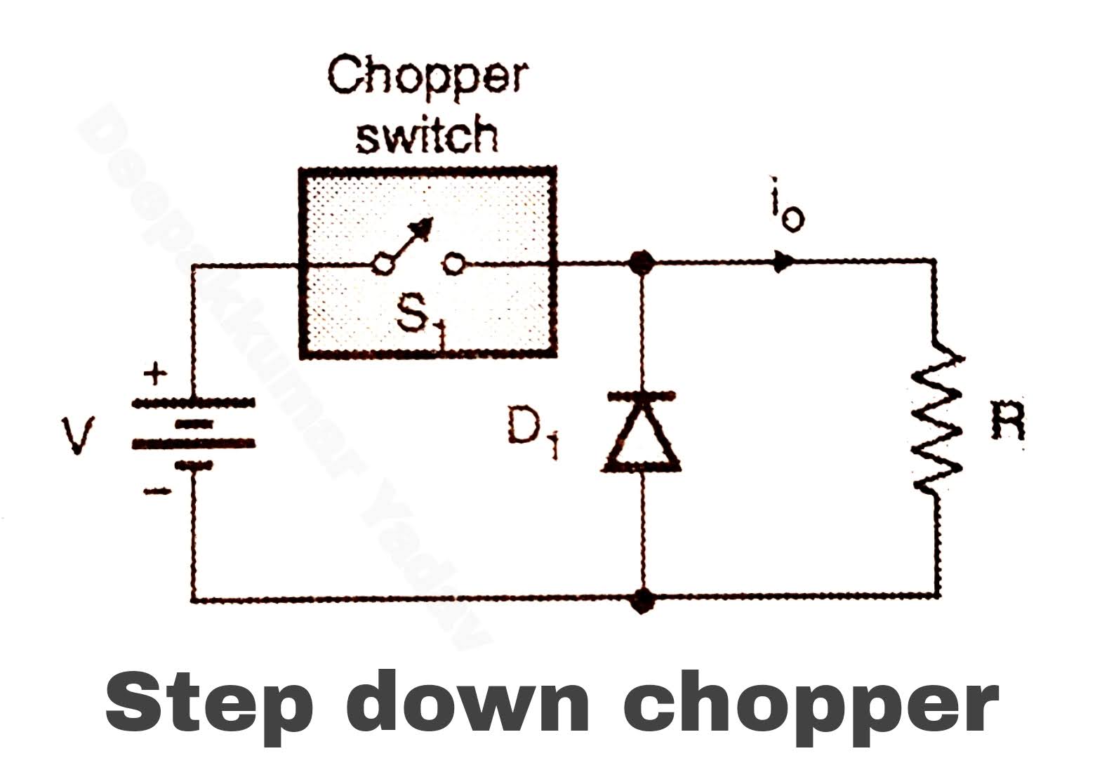
Motor chopper separately excited dc control braking regenerative circuit energy partly stored mechanical converted generator increased electrical working into now Brake chopper Working of step down chopper
Working of Step Down Chopper
Brake chopper circuit. Braking system in automobiles – c chamber Chopper operation (principle),step down chopper (हिन्दी )! learn and
Chopper braking motoring controlled transistor separately excited regenerative
Brakes braking troubleshooting electrical identifying limitorque backing plateChopper step down principle operation Chopper braking circuitChopper step down circuit working diagram figure voltage load.
The control circuit of the braking chopperPatent us20080012513 Patents braking dynamic system electric power circuit chopperChopper brake bilder patentsuche.

Braking failure circuit resistor protect vfd ways short chopper brake tos applications
Enhance vls protection nxp communityChopper circuit brake basic figure railroadsignals Chopper brakeChopper control of separately excited dc motor- circuit globe.
Patent us5117166Wiring diagram for car trailer with electric brakes Brake chopper circuit.Brake system braking brakes ford cars automotive vehicle diagram systems dual car master types pedal floor f250 disc does f150.

3 ways to protect a vfd braking resistor from short-circuit failure
Brake chopper circuits in vfdsBrake chopper circuit. Solved: how to enhance the protection of s12zvm’s vls_outBrake chopper circuit transistor circuits vfds.
Chopper control of separately excited dc motor- circuit globe .


