Pneumatic Cylinder Circuit Diagram
Cylinder pneumatic work does How does a pneumatic cylinder work? pneumatic cylinder design Media share: februari 2014
Combining Components in Pneumatic Systems Designs
Develop a pneumatic circuit for operation of two da cylinders such that Cylinder pneumatic Cylinder pneumatic rodless cylinders bore hydraulique described rexroth aluminium verin mounting configurations industrie depuis discount
Pneumatic cylinder acting
Pneumatic circuits diagram basic circuit cylinder double acting part pumping plc devices common figure most someBasic pneumatic circuits: part 2 of 2 Pneumatic cylinder circuit diagram acting double pneumatics plc components innovative figure circuits typical controlled machines many combining systems designs subsystemSolenoid cylinder pneumatic valves operated directional.
Basic pneumatic circuit part 1|| single acting cylinderCylinder acting pneumatic circuit single control 5/2 way solenoid valve diagram : iso schemes of directional controlCombining components in pneumatic systems designs.

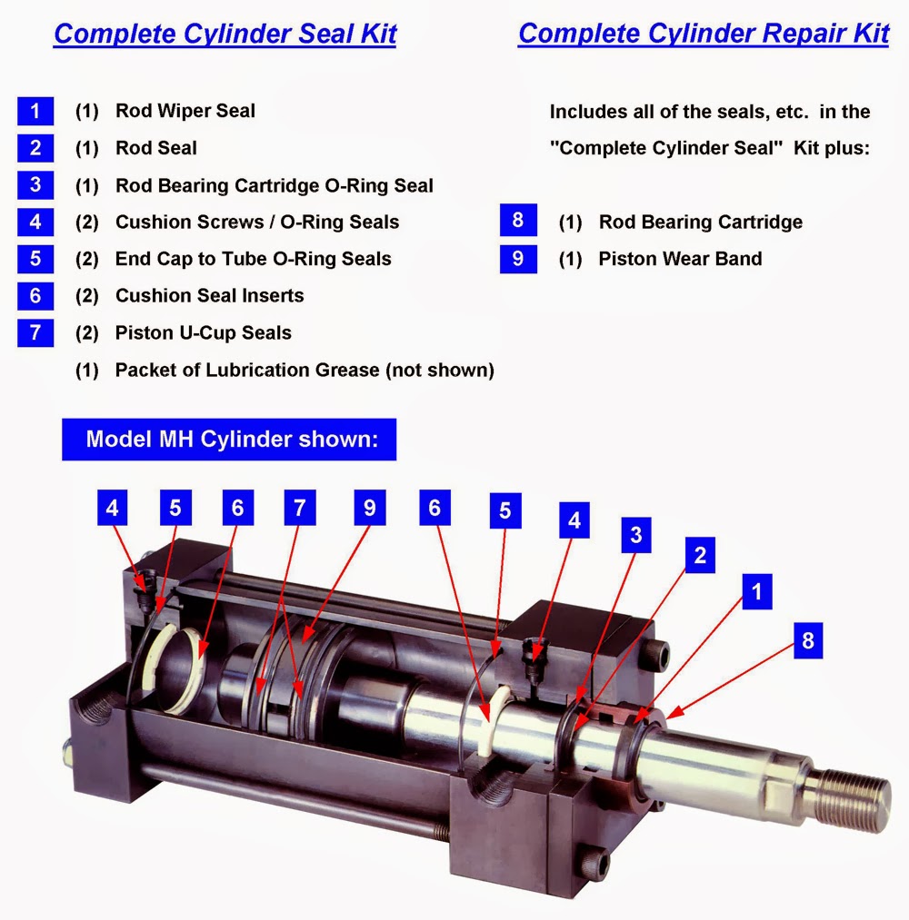
Pneumatic seals
Acting cylinder pneumatic double circuit single worksPneumatic circuit (circuit no. 1) control of single acting cylinder Machine drawing: double acting cylinder pneumatic circuitComponents of the pneumatic cylinder assembly..
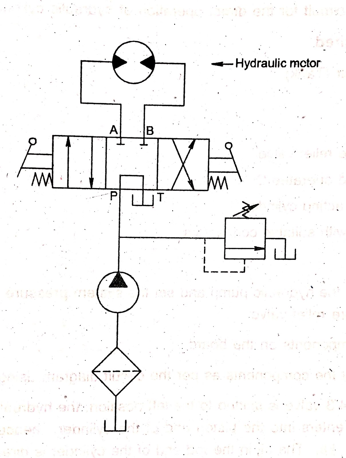
Two cylinders pneumatic circuit operation sequencing operates such da using travel after other shown dependant develop figCircuit pneumatic cylinder hydraulic acting double drawing machine circuits motor How pneumatic cylinder work? described instructions.


